Why Contact Resistance Matters in Power Connectors
Why Contact Resistance Matters in Power Connectors
Power connectors are often judged by the obvious things first.
How many amps can it handle?
What wire size does it accept?
What voltage is it rated for?
Will it fit in the space?
Those are all important questions, but there is another detail that can make or break a power connection:
Contact resistance.
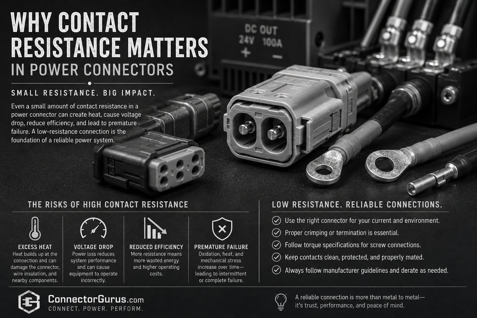
It may not sound exciting, but contact resistance is one of the biggest reasons a connector can run hot, lose efficiency, or eventually fail in the field.
In simple terms, contact resistance is the small amount of electrical resistance at the connection point between two conductive surfaces. In a power connector, that could be the mating contact interface, the crimp area, the screw clamp area, the spring contact, the terminal, or any other place where current has to pass through a mechanical connection.
A good power connector does not just carry current.
It carries current with as little unwanted resistance as possible.
What Is Contact Resistance?
Every electrical connection has some resistance. Even metal-to-metal connections are not perfect.
When two contacts touch, they may look smooth to the eye, but under magnification the surfaces are not perfectly flat. Current actually flows through many small contact points where the surfaces touch each other.
Those tiny contact points matter.
If the contact area is clean, tight, properly plated, properly crimped, and designed correctly, resistance stays low. If the connection is loose, contaminated, oxidized, poorly crimped, under-specified, or overheated, resistance can increase.
In a signal connector, contact resistance may cause intermittent signals, noise, or data problems.
In a power connector, contact resistance can create heat.
And heat is where the trouble starts.
Why Low Resistance Matters in Power Connectors
Power connectors often carry higher current than signal connectors. That means even a small amount of extra resistance can become a problem.
The basic idea is simple:
More resistance plus more current equals more heat.
As current flows through a resistive point, energy is lost as heat. In a low-current circuit, the heat may be minor. In a high-current circuit, that same small resistance can become a serious issue.
This is why power connector design is so focused on contact geometry, contact force, material selection, plating, termination quality, and temperature rise.
A connector may look fine on the outside while the internal contact interface is running hotter than expected.
Heat Rise Is the Real Concern
When contact resistance increases, heat rise usually follows.
That heat can affect the connector body, the contact plating, the wire insulation, the cable jacket, nearby components, and the long-term stability of the connection.
Heat can also create a cycle that gets worse over time.
A connection starts with slightly higher resistance.
The connection gets warmer.
The heat weakens spring force, damages plating, accelerates oxidation, or affects plastic materials.
Resistance increases more.
The connection gets even hotter.
Eventually, the connector may discolor, deform, loosen, arc, melt, or fail.
This does not always happen instantly. Sometimes it happens slowly over months or years, which makes it harder to catch.
Current Rating Does Not Tell the Whole Story
A connector’s current rating is important, but it should not be treated as the whole answer.
Current ratings depend on test conditions. Real applications may be very different from the conditions used in a datasheet.
A connector may be rated for a certain current in free air, but your application may place it inside an enclosure with limited airflow. It may be bundled with other cables. It may be near heat-producing components. It may have all contacts loaded at the same time. It may be installed in a warmer environment than expected.
That is why derating matters.
The real question is not just:
“Can this connector carry 30 amps?”
The better question is:
“Can this connector carry 30 amps continuously in my actual environment without excessive temperature rise?”
Those are very different questions.
Causes of High Contact Resistance
Contact resistance can increase for many reasons.
One common cause is poor termination. A bad crimp, loose screw, wrong ferrule, incorrect wire size, poor strip length, or improper tooling can all create higher resistance at the termination point.
Another cause is low contact force. Power contacts need proper mechanical pressure to maintain a stable electrical path. If the contact force is weak or reduced over time, resistance can increase.
Oxidation and contamination are also major issues. Dirt, oil, corrosion, moisture, or surface films can interfere with good metal-to-metal contact.
Plating mismatch can also matter. Mixing contact platings, such as tin and gold in the wrong application, can create long-term reliability concerns.
Mechanical stress is another factor. Vibration, cable movement, poor strain relief, repeated mating, or misalignment can all affect the contact interface.
Heat itself can also make the problem worse. Once a connector starts running hot, the materials and contact surfaces may degrade faster.
Real-World Scenario 1: The Connector That Was Rated Correctly but Still Ran Hot
A designer selects a power connector based on the published current rating. On paper, everything looks correct.
But in the actual equipment, the connector is installed inside a sealed enclosure with limited airflow. Several contacts are loaded at the same time, and the surrounding temperature is higher than expected.
During operation, the connector runs hotter than planned.
The issue is not necessarily that the connector was bad. The issue is that the rating was not evaluated against the actual installation conditions.
This is why current rating, temperature rise, airflow, and derating all have to be considered together.
Real-World Scenario 2: The Bad Crimp That Became a Heat Problem
A power connector is installed with the right contact and the right wire size, but the crimp was made with the wrong tooling.
At first, the connection seems fine. The equipment powers up. The connector passes a quick visual check.
But the crimp is not gas-tight or mechanically stable. Over time, resistance increases at the crimp point. Under load, the terminal heats up. Eventually, the connector shows discoloration or intermittent operation.
This is why correct tooling matters.
A power connector is only as good as the termination behind it.
Real-World Scenario 3: The Loose Screw Terminal
A screw terminal may look simple, but it still depends on proper installation.
If the screw is not tightened correctly, or if the wire strands creep or loosen over time, contact resistance can increase.
That extra resistance creates heat. The heat can loosen the connection further, and the cycle continues.
This is one reason torque specifications matter. It is also one reason ferrules can help in certain stranded-wire applications when used correctly.
Real-World Scenario 4: The Connector That Worked Until the Load Increased
A connector may perform fine for years at a lower current level. Then the system is upgraded, a larger load is added, or more equipment is powered from the same circuit.
The connector is now operating closer to its limit.
A small increase in contact resistance that was not a problem before can become a problem under higher load.
This is common when equipment gets modified without reviewing the original interconnect design.
Just because a connector worked before does not mean it is still right after the system changes.
Contact Resistance and Voltage Drop
Contact resistance does not only create heat. It can also contribute to voltage drop.
In some power systems, especially low-voltage systems, small voltage losses can matter.
A poor connection can reduce the voltage available to the load. That can cause equipment to behave incorrectly, reset, operate inefficiently, or fail under peak demand.
This is especially important in DC power systems, battery systems, control panels, robotics, industrial equipment, transportation, and data center power distribution.
The connector is part of the power path. It cannot be ignored.
Why Plating Matters
Contact plating helps protect the contact surface and support stable electrical performance.
Gold, tin, silver, and other plating options all have different strengths, weaknesses, and intended applications.
Gold is often used where low-level signals, corrosion resistance, or many mating cycles are important.
Tin is common in many power and industrial applications, but it can be more sensitive to fretting, oxidation, and plating compatibility concerns.
Silver can perform well in higher-current applications but may tarnish depending on the environment.
The important point is that plating is not just cosmetic. It affects contact performance, mating behavior, environmental resistance, and long-term reliability.
Using the wrong plating for the application can create problems that may not show up immediately.
Why Mating Force and Contact Design Matter
Good power connector design depends on controlled contact force.
The contact needs enough pressure to maintain a stable electrical connection, but not so much that mating becomes difficult or damages the contacts.
Spring properties, contact shape, material thickness, plating, and mechanical alignment all play a role.
A well-designed contact system maintains low resistance over time, even through temperature changes, vibration, and normal service conditions.
This is one of the reasons cheap or poorly designed connectors can become a risk in power applications.
The outside may look similar, but the contact system inside may not perform the same.
Signs of Contact Resistance Problems
Possible signs of excessive contact resistance include:
Connector discoloration.
Melted or softened plastic.
Burn marks.
Warm or hot connector body.
Intermittent power loss.
Voltage drop under load.
Nuisance resets.
Smell of overheated insulation.
Loose terminals.
Visible corrosion.
Damaged plating.
Repeated failures at the same connection point.
Any connector that is running hot should be taken seriously.
A warm connector is not always a failure, but it should be evaluated against the expected temperature rise and manufacturer specifications.
What Buyers and Engineers Should Ask
Before selecting a power connector, it helps to ask practical questions:
What current will the connector carry continuously?
What is the maximum current during startup or peak load?
What is the ambient temperature?
Will the connector be inside an enclosure?
Is there airflow around the connector?
Are multiple contacts carrying current at the same time?
Is derating required?
What wire size is being used?
What termination method is required?
What tooling is specified?
What plating is used?
How many mating cycles are expected?
Will the connector see vibration or movement?
Is strain relief required?
Is the connector easy to inspect and service?
Has temperature rise been tested in the real application?
These questions are not overkill. They are the difference between a connector that works on paper and a connector that works reliably in the field.
How to Reduce Contact Resistance Risk
The best way to reduce contact resistance problems is to treat the connector as part of the electrical system, not just a hardware item.
Use the correct connector for the current and environment.
Follow the manufacturer’s ratings and derating guidance.
Use the correct wire size.
Use the correct crimp tooling.
Follow strip length and termination instructions.
Torque screw terminals correctly.
Avoid mixing incompatible platings.
Protect the connector from contamination and moisture.
Provide proper strain relief.
Avoid unnecessary vibration and cable movement.
Test under real operating conditions.
A power connector should not be selected only by amp rating and price.
It should be selected by how well it maintains a stable, low-resistance connection over time.
My Practical Take
Contact resistance sounds like a small detail, but in power connectors it can become a big problem.
A few extra milliohms may not look like much on paper, but under load it can create heat, voltage drop, efficiency loss, and long-term reliability issues.
Many connector failures are not sudden mysteries. They often start as small resistance problems caused by poor termination, wrong tooling, loose connections, contamination, plating issues, or using the connector too close to its real-world limit.
The goal is not just to make a connection.
The goal is to make a connection that stays stable, cool, and reliable for the life of the equipment.
Final Thought
Power connectors do important work quietly.
When they are selected, installed, and maintained correctly, nobody thinks about them.
When contact resistance becomes a problem, everybody notices.
That is why the small details matter: the right connector, the right contact, the right plating, the right tooling, the right wire, and the right installation.
A low-resistance connection is not just better electrically.
It is safer, cooler, more efficient, and more reliable.
