High-Speed Connectors: Why Shielding Matters
High-Speed Connectors: Why Shielding Matters
High-speed connectors can be a little misleading.
From the outside, they may look like just another connector. They plug in, they latch, they pass signals, and everything seems straightforward. But once you start dealing with high-speed data, the connector is no longer just a mechanical connection between two points.
It becomes part of the signal path.
That means the connector, cable, shield, ground path, contact layout, plating, termination method, and even the way the cable is routed can all affect performance.
One of the biggest parts of that discussion is shielding.
What Is Shielding?
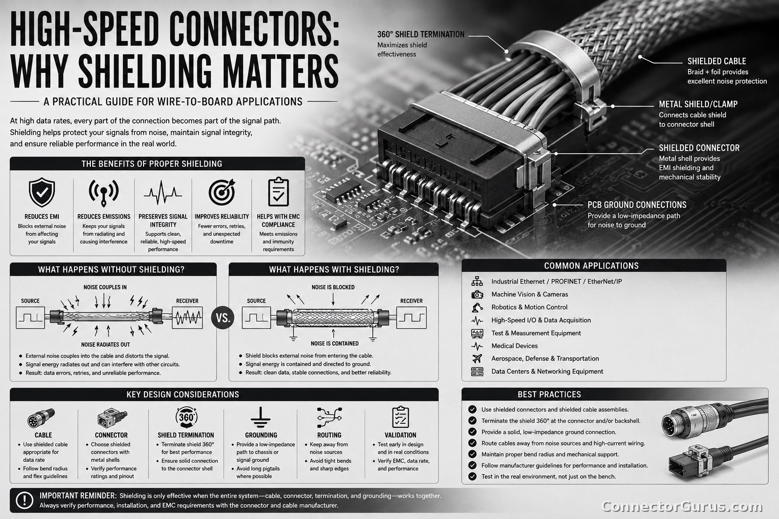
Shielding is a conductive barrier used to help protect signals from electrical noise and to help contain noise generated by the signal itself.
In simple terms, shielding helps keep unwanted noise out and helps keep the signal’s own energy from causing problems elsewhere.
In a cable assembly, shielding may include foil, braid, drain wires, metal shells, shielded backshells, conductive gaskets, or shielded connector housings.
In a connector, shielding may involve the metal shell, shield termination, ground contacts, internal shielding, 360-degree shield connection, or the way the cable shield bonds to the connector body.
The details matter, especially at higher data rates.
Why Shielding Matters More at High Speed
Low-speed signals are often more forgiving. A basic connection may work fine even if the wiring is not perfect.
High-speed signals are different.
As data rates increase, the signal becomes more sensitive to noise, impedance changes, reflections, crosstalk, and poor grounding. What worked at a lower speed may not work at a higher speed.
At high speed, the connector and cable are not just carrying electricity. They are carrying fast-changing signals that need a controlled path.
Shielding helps protect that path.
EMI and EMC: The Practical Side
Two terms that come up often with shielding are EMI and EMC.
EMI stands for electromagnetic interference. That is the unwanted electrical noise that can disturb a signal or be emitted from a device.
EMC stands for electromagnetic compatibility. That means the product can operate properly in its environment without causing or suffering from too much interference.
In the real world, this matters because high-speed cables and connectors can act like antennas if they are poorly shielded or poorly grounded.
That can create communication errors, failed compliance testing, random resets, lost data, intermittent faults, or noise problems in nearby circuits.
Shielding Helps Protect Signal Integrity
Signal integrity is about keeping the signal clean enough that the receiving device can understand it correctly.
Poor shielding can allow outside noise to interfere with the signal. It can also allow the signal to radiate outward and create problems for other parts of the system.
Good shielding helps reduce those risks.
It supports cleaner communication, better noise immunity, and more predictable performance.
This becomes especially important in applications such as industrial Ethernet, machine vision, robotics, high-speed I/O, data centers, test equipment, medical electronics, aerospace, transportation, and automation systems.
Crosstalk Between Signals
Crosstalk happens when one signal interferes with another signal nearby.
In high-speed connectors and cables, this can happen between pairs, between adjacent contacts, or between different signal groups.
Shielding, contact layout, pair spacing, cable construction, and grounding all help control crosstalk.
This is one reason high-speed connector design is more complicated than simply adding more pins into a smaller space.
The physical arrangement of the contacts matters.
Impedance Control
Many high-speed systems require controlled impedance.
Impedance is not the same as simple DC resistance. It describes how a signal behaves as it travels through the connector, cable, and PCB path.
If the impedance changes too much at the connector interface, the signal can reflect back toward the source. These reflections can distort the signal and cause communication problems.
Shielding and connector design help maintain a more controlled electrical environment around the signal path.
That is why high-speed connectors often have very specific layouts, grounds, shields, and mating geometry.
Grounding the Shield Correctly
A shield is only as good as the way it is terminated.
One common mistake is assuming that having a shielded cable automatically means the system is properly shielded. That is not always true.
If the shield is poorly connected, left floating, connected through a long drain wire, or terminated inconsistently, shielding effectiveness can be reduced.
In many high-speed and industrial applications, a 360-degree shield termination is preferred because it provides a more complete connection between the cable shield and connector shell.
The goal is to give noise a low-impedance path to ground, instead of allowing it to interfere with the signal.
The Connector Shell Matters
For shielded high-speed connectors, the shell is not just there for strength or appearance.
A metal shell can help provide shielding continuity through the connector interface. It can also help connect the cable shield to the equipment ground or chassis ground.
Plastic connector housings can still be appropriate in some applications, but when shielding is needed, the connector design must support that requirement.
The mating interface, shell material, plating, backshell, cable clamp, and grounding method all become part of the shielding system.
Cable Shielding and Connector Shielding Must Work Together
A shielded connector paired with an unshielded cable may not solve the problem.
A shielded cable with a poorly terminated connector may not solve the problem either.
The cable and connector have to work together as a system.
That includes:
Cable Type
The cable should be rated for the data speed, impedance, shielding, flex life, environment, and application.
Shield Construction
The shield may be foil, braid, or a combination of both. Each has different benefits.
Connector Termination
The cable shield needs to be terminated properly to the connector or backshell.
Ground Path
There needs to be a clear, intentional grounding approach.
Application Environment
The environment may include motors, drives, relays, welders, power cables, RF sources, or other noise-generating equipment.
What Happens When Shielding Is Poor?
Poor shielding does not always create an obvious failure right away.
Sometimes the system works in the lab, then fails in the field.
Sometimes it works on a short cable, then fails on a longer one.
Sometimes it works until a motor starts, a drive turns on, a relay switches, or another cable is routed too close.
Possible problems include:
Data Errors
Noise can corrupt the signal and cause communication retries, packet loss, or failed communication.
Intermittent Operation
The system may fail only under certain conditions, making the problem hard to reproduce.
Failed EMC Testing
The product may radiate too much noise or be too sensitive to outside noise.
Reduced Cable Length
Poor shielding can limit how far the signal can travel reliably.
Lower Speed Performance
A system designed for high speed may only work reliably at a lower speed.
Equipment Malfunctions
Noise can affect nearby electronics, sensors, controls, or communication devices.
Real-World Example
A high-speed connection may work perfectly on a bench with a short cable in a quiet environment.
Then the same design is installed on a machine near servo drives, motors, power wiring, and moving cable carriers.
Suddenly, the data link becomes unstable.
The connector did not change. The signal did not change. The environment changed.
That is where shielding, grounding, cable routing, and connector selection can make the difference between a stable system and a troubleshooting nightmare.
Shielding Is Not a Band-Aid
Shielding is important, but it is not a magic fix for a poor design.
A shielded connector cannot always overcome the wrong cable, poor grounding, bad routing, incorrect impedance, poor PCB layout, or mismatched components.
The best results come when shielding is considered early in the design.
That means selecting the right connector, cable, termination method, grounding strategy, and routing approach from the beginning.
What to Check Before Selecting a Shielded High-Speed Connector
Before selecting a high-speed connector, it is worth checking several details:
Data Rate
What speed does the signal need to support?
Protocol
Is it Ethernet, USB, HDMI, DisplayPort, PCIe, LVDS, SerDes, camera link, or another high-speed interface?
Impedance
Does the system require a specific impedance, such as 50 ohm, 85 ohm, 90 ohm, or 100 ohm differential?
Shielding Requirement
Does the application require shielded cable, shielded connector, shielded backshell, or 360-degree shield termination?
Grounding Strategy
How will the shield connect to chassis ground, signal ground, or equipment ground?
Cable Length
How long is the cable, and is that length supported at the required speed?
Environment
Will the cable be near motors, drives, power wiring, welders, RF sources, or high-current conductors?
Flexing and Movement
Will the cable be stationary, flexing, moving in a cable track, or exposed to vibration?
EMC Requirements
Does the product need to pass specific emissions or immunity testing?
Manufacturer Guidance
Does the connector manufacturer provide recommended cable types, mating connectors, backshells, termination instructions, and performance data?
My Practical Take
My view is that shielding should not be treated as an afterthought in high-speed connector applications.
If the signal matters, the shield matters.
A high-speed connector is part of the electrical design, not just a hardware choice. The cable, connector, shield, ground path, and routing all work together.
Using the right shielded connector and cable assembly may cost more up front, but it can save a lot of time later. It can reduce noise problems, improve reliability, support compliance, and help avoid field failures that are difficult to diagnose.
The cheapest connector is not always the cheapest solution if it creates troubleshooting time, redesign work, or unreliable communication.
Final Thought
High-speed connectors need more than a good mechanical fit.
They need a clean signal path, proper shielding, controlled impedance, stable grounding, and the right cable assembly for the application.
Poor shielding can create problems that are intermittent, environment-dependent, and hard to track down. Good shielding helps the system perform the way it was designed to perform.
The best practice is simple: choose the connector and cable as a system, verify the shielding and grounding method, follow the manufacturer’s recommendations, and do not wait until the end of the design to think about EMI, EMC, and signal integrity.
ConnectorGurus.com note: Always verify high-speed connector performance, shielding, grounding, cable construction, impedance, data-rate capability, mating compatibility, and EMC requirements against the specific manufacturer’s documentation and applicable standards for your application.
